


Gear parameter diagram
Publication time: 2019-12-02 Website: https://ptogearboxes.com Edit: EP
Diagram of gear parameters:
XNUMX. Pressure angle:

1. Pressure angle: The angle between the direction line of the normal pressure at any point on the involute line (that is, the normal line of the involute at that point) and the speed direction of the point is called the pressure angle of the point.
2. In the left figure below, ak is the pressure angle at point K on the involute line.It can be seen from the figure: cosak=ON/OK=rb/Rk.
3. In the right figure below, the pressure angle is the angle between the radius line and the tangent of the tooth shape, a is the pressure angle, because a'=a, so α'is also the pressure angle.
4. Generally speakinggearThe pressure angle refers to the pressure angle on the index circle, represented by a, and specifies the standard value of the pressure angle on the index circle, called the standard pressure angle, and our country takes a=20°.

5. The pressure angle of each point on the involute line varies.The pressure angle on the base circle is zero, and the pressure angle on the addendum circle is the largest.

XNUMX. End face:
The plane perpendicular to the axis of the gear.
XNUMX. Dharma:
The plane perpendicular to the tooth line of the gear.
XNUMX. Tooth line:
The intersection line of the tooth surface and the indexing cylindrical surface.
XNUMX. Base circle:
The generating line forming the involute makes a purely rolling circle on it.
XNUMX. Tooth width b:
The size of the gear teeth in the axial direction.
XNUMX. Reference rack:
A rack cut according to its standard gear specifications.
XNUMX. Pitch circle:
The occlusal contact point of the two gears on the center line leaves a track on each gear.
XNUMX. Pitch diameter:
Pitch diameter.
XNUMX. Index circle:
Between the addendum circle and the root circle, a circle with a diameter of d is specified as the basis for calculating the size of each part of the gear.
The size of the index circle is determined by the tooth pitch and the number of teeth.
The indexing circumference dπ=mz, d= pz/π.

XNUMX. Tooth pitch:
The length of the indexing arc between two adjacent teeth on the same side profile is represented by p.
XNUMX. Modulus:
The ratio of the tooth pitch P to π is expressed in m.
XNUMX. Tooth root height:
The radial height from the index circle to the tooth root circle is expressed in hf.
XNUMX. Tooth top height:
The radial height from the index circle to the addendum circle is expressed in ha.
XNUMX. Total tooth height:
The radial height from the addendum circle to the root circle is represented by h.
XNUMX. Top clearance:
After the two gears are assembled, the gap distance left by the two meshing teeth in the radial direction is denoted by C.
XNUMX. Number of teeth:
Looking down from the reference plane, if measured clockwise, the tooth or slot defines the slot number as 1,2, XNUMX.., and Z is the total number of teeth.

XNUMX. Tooth surface:

Two methods for judging whether a tooth surface is left or right are as follows. For a tooth surface, no matter which method is used, the result is the same:
1. Standing outside the gear and looking at the teeth, the left hand is the left tooth surface, and the right hand is the right tooth surface.
2. Standing in the center of the gear and looking at the cogging, the left hand is the left tooth surface, and the right hand is the right tooth surface.
XNUMX. The modulus of the law surface:
The modulus of the normal tooth profile of the helical gear.Normal face modulus (normal face pressure angle, etc.) is used for gear manufacturing and strength checking.
Twenty. End face modulus:
The modulus of the tooth profile of the helical gear.The end face modulus (end face pressure angle, etc.) is used for structural size calculation.
1. For spur gears, the conversion formula of end face modulus mt and normal face modulus mn is as follows:

2. For helical gears, the conversion formula of end face modulus mt and normal face modulus mn is as follows:

(Β: helix angle)
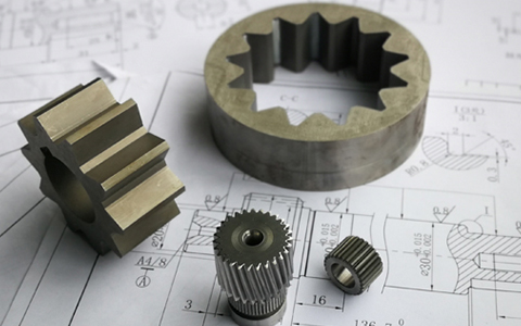
Gear type description:
1. It can be divided into straight teeth, oblique teeth and herringbone teethCylindrical gearTransmission, this type of product is generally used for transmission between parallel shafts.
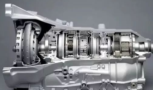
2. It can be divided into helical gear transmission,Turbine shaftTransmission, such products are generally used for transmission between vertical staggered shafts.
3. Internal gear transmission is generally used for the same direction transmission between parallel shafts.
4. Rack and pinion transmission is generally used for the conversion of rotary motion and linear motion.
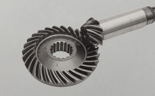
5. Straight bevel gear transmission is generally used for transmission between intersecting shafts.

Standard spur gear size calculation formula table:

The correct meshing condition of the spur gear: the modulus and the pressure angle are equal.
Shift gear:
The involute gear is processed by the generative method. When the center line of the rack cutter is tangent to the index circle of the gear blank, the processed gear is called a standard gear.
If other conditions remain unchanged, only change the relative position of the tool and the gear blank, so that the center line of the tool is no longer tangent to the index circle of the gear blank, so that the machined gear is called a shifted gear.
1. The distance between the center line of the rack tool and the index circle of the gear blank is called the displacement, which is expressed by the product xm of the displacement coefficient x and the gear module m.
2. When the tool is far away from the gear center, x>0, such a gear is called a positive displacement gear;
3. On the contrary, when the tool is closer to the gear center, x<0, such a gear is called a negative displacement gear.

4. Compared with standard gears, since the base circle has not changed, the tooth profile curve is the same involute, except that the positively modified gear uses a larger radius of curvature, while the negatively modified gear uses a larger radius of curvature. A small section of involute.
5. Compared with standard gears, there is no change in modulus, number of teeth, and pressure angle of shifted gears.
6. Normal non-shift gear at the index circle: gear tooth thickness = tooth groove width; shift gear, change the position of the tool during processing (outward or inward than the normal position), so: gear tooth thickness ≠ Cogging width.
7. In the positive displacement, the tooth profile curve segment is far from the base circle, the addendum circle and the tooth root circle also increase correspondingly, the tooth root height decreases, the tooth tip height increases, and the indexing circle tooth thickness and tooth root circle The tooth thickness is increased, but the tooth top is easy to become sharp;

8. In negative displacement, the tooth profile curve segment is closer to the base circle, the addendum circle and the root circle are correspondingly reduced, the tooth root height increases, the tooth tip height decreases, and the indexing circle tooth thickness and tooth root circle The tooth thickness is reduced.
The above is a description of the relevant content of the gear parameter diagram, including but not limited to, if you have more questions or related product processing needs, you can click on the consultation window on the right side of EP for free consultation.

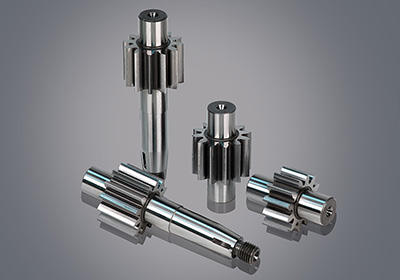
![Oil pump gear [customized]](ptogearboxes/xiaoE/upload/file/img/2020/10/5f9a8130d4e57.jpg)
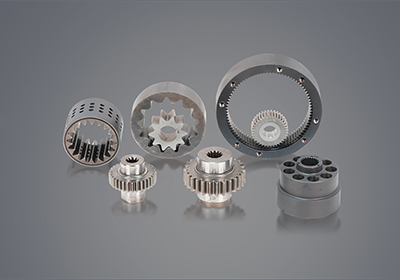
![Encoder gear [customized]](ptogearboxes/xiaoE/upload/file/img/2020/10/5f9a7c8ae4b27.jpg)