


Principle explanation of helical gear cutting processing method
Publication time: 2020-01-13 Website: https://ptogearboxes.com Edit: EP
As shown in Figure 1, the tooth width of the helical gear has an angle with the axis![]() The spiral has a certain lead.In addition to hobbing during processingSpur gearThe three basic movements of the tool are the tool rotation
The spiral has a certain lead.In addition to hobbing during processingSpur gearThe three basic movements of the tool are the tool rotation![]() , Gear blank rotation (divided teeth)
, Gear blank rotation (divided teeth)![]() And tool tooth blank axial feed
And tool tooth blank axial feed![]() In addition, the tooth blank must also have corresponding additional movement
In addition, the tooth blank must also have corresponding additional movement![]() (That is, when the tool moves from point A to point a, point B of the workpiece should be turned to point a).
(That is, when the tool moves from point A to point a, point B of the workpiece should be turned to point a).

The calculation method of the additional motion of 2 kinds of hobbing helical gears:
1. Calculate based on the rotation of the worktable:

as shown in picture 2.Set the right-handed hob to process the left-handed gear. If the tooth blank does not make additional movement, the hob must move along the axis from point B to point a, and its speed is![]() .Because the hob teeth are distributed on the hob spiral, the hob can be rotated additionally
.Because the hob teeth are distributed on the hob spiral, the hob can be rotated additionally![]() Instead of parallel movement
Instead of parallel movement![]() .Its direction and hob rotation speed
.Its direction and hob rotation speed![]() The direction is opposite, the value has a certain transmission ratio with the tooth blank, that is, when the tooth blank rotates 1 revolution, the hob has
The direction is opposite, the value has a certain transmission ratio with the tooth blank, that is, when the tooth blank rotates 1 revolution, the hob has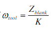 In addition to rotation, there should be additional rotation
 (Usually K=1).
That is, when the additional rotation is calculated on the basis of the workpiece, there are: the gear blank has rotated 1 rotation, and the hob has rotated turn.Among them, the + sign is used for the direction of the spiral of the tool and the workpiece, and the-sign is used for the spiral direction of the tool and the workpiece.
2. Calculate based on hob rotation:

Based on the rotation of the hob, the hob is regarded as the head end of the transmission chain, and the rotating work is shown in Figure 3.Assuming that the right-handed hob is used to process the right-handed helical gear, the tooth movement is removed![]() In addition, there should be additional movement (that is, when the tool moves from point A to point a, the workpiece turns from a to point B), set the lead of the tooth blank as H,
In addition, there should be additional movement (that is, when the tool moves from point A to point a, the workpiece turns from a to point B), set the lead of the tooth blank as H,

In the formula, K- the number of cutter heads, usually 1;![]() -The number of teeth of the gear being machined;
-The number of teeth of the gear being machined;![]() -The amount of feed along the axis of the machined wheel per hob revolution, unit
-The amount of feed along the axis of the machined wheel per hob revolution, unit![]() .
.
Therefore, the number of revolutions of the gear blank when the hob rotates one revolution is:

When machining a left-handed helical gear with a right-handed hob, the tooth blank must also have a corresponding additional movement![]() (That is, when the tool moves from point A to a, point a of the workpiece should be retracted to point B), so the "+" sign in the above formula should be changed to "-".
(That is, when the tool moves from point A to a, point a of the workpiece should be retracted to point B), so the "+" sign in the above formula should be changed to "-".
Combining the two situations, there is a knife turned Turn, the teeth still turn
 turn.Among them, the "+" sign is used for the tool and the workpiece helix direction is the same, the "-" sign is for the tool and the workpiece helix direction is opposite.
The above is what I shared with you todayhelical gearThe explanation of the principle of the cutting processing method, including but not limited to, if you have any unclear points or related needs, you can consult EP free of charge.

![Oil pump gear [customized]](ptogearboxes/xiaoE/upload/file/img/2020/10/5f9a8130d4e57.jpg)
![Encoder gear [customized]](ptogearboxes/xiaoE/upload/file/img/2020/10/5f9a7c8ae4b27.jpg)