


ug gear drawing method (for reference)
Publication time: 2020-04-16 Website: https://ptogearboxes.com Edit: EP
ug gear drawingThe following is for reference. If you have any unclear points or related processing requirements, you can consult EP free of charge.
The following ug drawshelical gearThe method is for your reference.The number of teeth is less than 41, and the ones greater than 41 are better drawn.
Open the tool-expression and enter the parameters.
After confirming, open the law curve, click according to the equation in the law function dialog box that appears, and determine the parameter expressions of X, Y, and Z in sequence. Do not change anything, just click OK.
In the end, the base point and the position of the coordinate system are also determined, and the obtained involute is as shown in the figure below.

Involute
Open the basic curve, click on the circle, and draw the addendum circle and the base circle in turn.
The center of the circle is the origin. When entering the diameter, you can directly enter da and d, because there are their equations in the expression.

Base circle and addendum circle
Enter the sketch environment and use the xy plane as the reference plane.Create a sketch.Draw the root circle with the far point as the center, and then draw a straight line with the intersection point of the involute and the base circle and the center of the base circle.

Draw a straight line, with the end point of the involute as the starting point, and constrain the degree between the two straight lines to be 90/Z as shown in the figure.

Click the guide fillet, select the line drawn in the previous step and the tooth root circle, and enter r for the fillet radius, as shown in the figure.

Click the transform in the editor (Ctrl+T shortcut key), select the curve, as shown in the figure below (yellow line).

Click OK, and then click to mirror with a straight line.

Select two points, and then select the fillet, the intersection point of the root circle and the center of the base circle.Click Copy, and the result is shown in the figure.

Delete the extra curve, and then exit the sketch environment.As shown below.

Connect the two end points of the involute with a straight line, as shown in the figure.

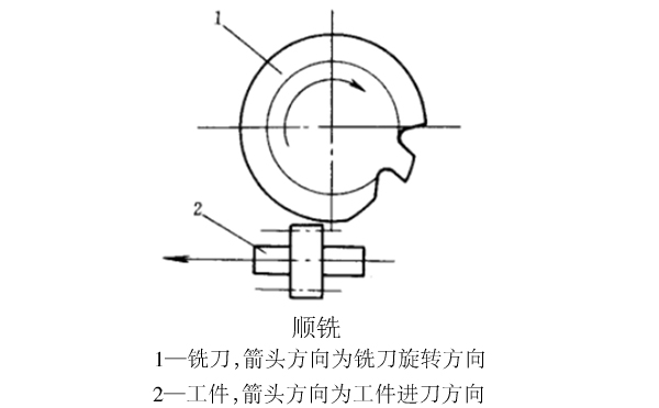
Begin drawing the spiral line below.Open the spiral in the curve.

Enter 0.8 in the number of turns, because my tooth thickness is more than 200, so choose 0.8, if you draw a smaller one, you can choose a smaller one, and enter P in the pitch.The radius is da/2.As shown in the figure after confirming.

Connect the intersection point and center of the spiral line with the addendum circle with a straight line, as shown in the figure.

Connect the intersection point and center of the involute with the addendum circle with a straight line, as shown in the figure.

Measure the angle between the straight line in the middle and the straight line on both sides with the measuring angle tool in the analysis, and write it down.

The angle is 3.7122.

The angle is 9.3286.
Select the spiral line just drawn, click Rotate around the point in the transform, rotate the center of the circle in the point dialog box, enter 3.7122 in the angle, and click Copy.The result is shown in the figure.

The same method is used to transform the helix, the angle is -9.3286, and the result is shown in the figure.

Choose Insert, Sweep, Sweep.As shown.

Select the section curve as shown in the figure (yellow curve).

The guide curve is three spirals.After clicking OK, as shown in the figure.

Select the feature of the sweep, and then select the rotation around the point in the transform.As shown in the figure.

Take the center of the circle as the center of rotation, enter 360/z in the angle, and keep clicking copy after confirming, the result is shown in the figure.

Create a cylinder with the far point as the center and the diameter da and height 270 as shown in the figure.

Find the difference, the cylinder is the target body, the copied feature is the total concrete, and the final drawngearThe result is shown in the figure.

The above ug gear drawing method includes but not limited to, if there is any update without notice!
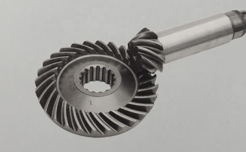
<Previous article:Straight bevel gear
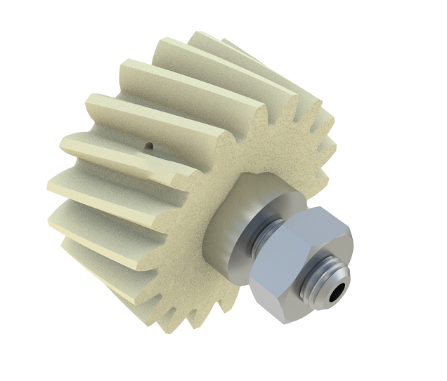
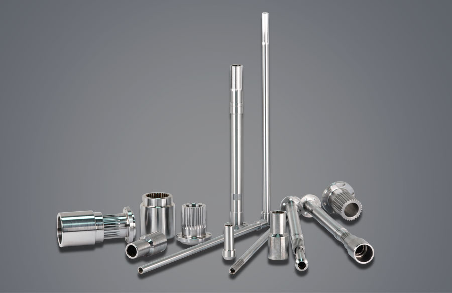
>Next:Damping gear

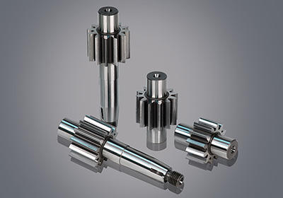
![Oil pump gear [customized]](ptogearboxes/xiaoE/upload/file/img/2020/10/5f9a8130d4e57.jpg)
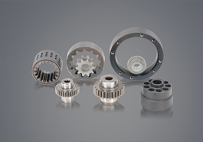
![Encoder gear [customized]](ptogearboxes/xiaoE/upload/file/img/2020/10/5f9a7c8ae4b27.jpg)