


Straight tooth cylindrical external gear shaping process (for reference)
Publication time: 2020-05-28 Website: https://ptogearboxes.com Edit: EP
Straight tooth cylindrical external gear shaping process: the selection of tool teeth, tool installation and adjustment related instructions are as follows, for reference.
Selection of the number of tool teeth:
When the gear structure and equipment allow, choose a tool with a larger number of teeth.For the smaller number of teethgear, In order to avoid undercutting, the following table should be attached.


Installation of gear shaper:
Disk-shaped and bowl-shaped gear shaper cutters are installed on the main shaft of the gear shaper based on the mounting hole and supporting end surface; tapered shank gear shaper cutters are installed on the cone of the gear shaper main shaft based on the shank cone , Tighten it with a tie rod.The installation requirements are shown in the table below.

Adjustment of gear shaping tool:
1. Calculation of the stroke length of the gear shaper tool
The stroke length L is determined by the gear width B and the gear shaper overrun ΔL, as shown in the figure below.Overrun △L=1.5~3.0mm.


2. Reciprocating stroke speed of gear shaper n (calculation of times/min)

3. Selection of circumferential feed of gear shaper cutter
Generally, the feed is 0.015~0.15m per reciprocating stroke.

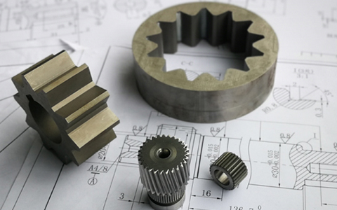
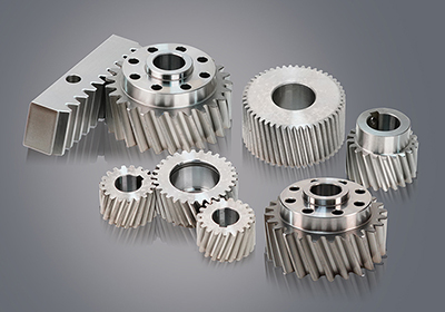
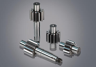
![Oil pump gear [customized]](ptogearboxes/xiaoE/upload/file/img/2020/10/5f9a8130d4e57.jpg)
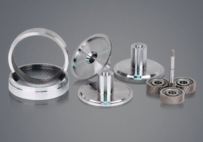
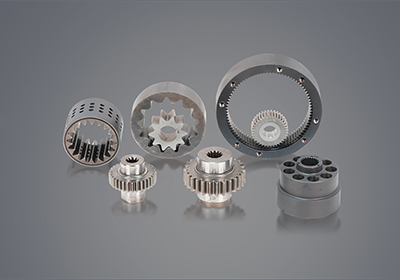
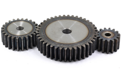
![Encoder gear [customized]](ptogearboxes/xiaoE/upload/file/img/2020/10/5f9a7c8ae4b27.jpg)